


The
HRLV-MaxSonar-EZ sensor line is the most cost-effective solution for
applications where precision range-finding, low-voltage operation, space saving
and low-cost are needed. This sensor component module allows users of other
more costly precision rangefinders to lower the cost of their systems without
sacrificing performance.
Additionally,
this sensor line allows cost-sensitive designers to choose this precision
sensor as a performance upgrade over other lower performance sensors.
The
HRLV-MaxSonar-EZ sensor line provides high accuracy and high resolution ultrasonic
proximity detection and ranging in air, in a package less than one cubic inch.
This sensor line features 1-mm resolution, target-size and operating-voltage
compensation for improved accuracy, superior rejection of outside noise
sources, internal speed of-sound temperature compensation and optional external
speed-of-sound temperature compensation. This ultrasonic sensor detects objects
from 1-mm to 5-meters, senses range to objects from 30-cm to 5-meters, with
large objects closer than 30-cm typically reported as 30-cm. The interface
output formats are pulse width, analog voltage, and serial digital in either
RS232 or TTL. Factory calibration is standard.
Precision
Ultrasonic Range Sensing
•
Range-finding at a fraction of the cost of other precision
rangefinders.
•
Reading-to-reading stability of 1-mm at 1-meter is typical.
•
Accuracy is factory-matched at 1-meter to 0.1% providing a
typical large target accuracy of 1% or better for most voltages.
•
Calibrated acoustic detection zones allows users to choose
the part number with the detection zone that, matches their specific
application.
•
Compensation provided for target size variation and operating
voltage range.
•
Internal temperature compensation is standard.
•
Optional external temperature compensation.
Very
Low Power Requirements
•
Wide, low supply voltage requirements eases battery powered design.
•
Low current draw reduces current drain for battery operation.
•
Fast first reading after power-up eases battery requirements.
Easy
to use Component Module
• Stable and reliable range readings and
excellent noise rejection make the sensor easy to use for most users.
•
Easy to use interface with distance provided in a variety of
outputs.
•
Target size compensation provides greater consistency and
accuracy when switching targets.
•
Sensor automatically handles acoustic noise.
•
Sensor ignores other acoustic noise sources.
•
Small and easy to mount.
•
Calibrated sensor eliminates most sensor to sensor
variations.
•
Very low power ranger, excellent for multiple sensor or
battery based systems.
Range
Outputs
•
Pulse width, (1uS/mm).
•
Analog Voltage, (5mm resolution).
•
Serial, (RS232 or TTL, where TTL format by solderable jumper
or volume orders available as no-cost factory installed jumper).
General
Characteristics
•
Low cost ultrasonic rangefinder.
•
Sensor dead zone virtually gone.
•
Size less than 1 cubic inch with easy mounting.
•
Object proximity detection from 1-mm to 5-meters.
• Resolution of 1-mm.
• Distance sensor from 30-cm to 5-meters.
• Excellent To Mean Time Between Failure
(MTBF).
• Triggered operation yields a real-time.
• 100mS measurement cycle.
• Free run operation uses a 2Hz filter,
with 100mS measurement and output cycle.
• Operating temperature range from
-15°C to +65°C, provided proper frost prevention is employed.
• Operating voltage from 2.5V to
5.5V.
• Nominal current draw of 2.5mA
at 3.3V, and 3.1mA at 5V.
Applications
& Uses
•
Bin level measurement.
•
Proximity zone detection.
•
People detection.
•
Robots ranging sensor.
•
Autonomous navigation Distance measuring.
•
Long range object detection.
•
Environments with acoustic and electrical noise.
•
Height monitors.
•
Auto sizing.
HRLV-MaxSonar®-EZ™
Pin Out

Pin
1- Temperature Sensor Connection: Leave this
pin unconnected if an external temperature sensor is not used.
Pin
2- Pulse Width Output: This pin outputs a
pulse width representation of the distance with a scale factor of 1uS per mm.
Output range is 300uS for 300-mm to 5000uS for 5000-mm. Pulse width output is
up to 0.5% less accurate than the serial output.
Pin
3- Analog Voltage Output: On power-up, the
voltage on this pin is set to 0V, after which, the voltage on this pin has the
voltage corresponding to the latest measured distance. This pin outputs an
analog voltage scaled representation of the distance with a scale factor of
(Vcc/5120) per 1-mm. The distance is output with a 5-mm resolution. (This
output voltage is referenced to GND, Pin 7.) The analog voltage output is
typically within ±10-mm of the serial output.
Using
a 10bit analog to digital convertor, one can read the analog voltage bits (i.e.
0 to 1024) directly and just multiply the number of bits in the value by 5 to
yield the range in mm. For example, 60 bits corresponds to 300-mm (where 60 * 5
= 300), and 1000 bits corresponds to 5000-mm (where 1000 * 5 = 5000-mm).
A
5V power supply yields~0.977 mV per 1 mm. Output voltage range when powered
with 5V is 293mV for 300-mm, and 4.885V for 5000-mm.
Pin
4- Ranging Start/Stop: This pin is internally
pulled high. If this pin is left unconnected or held high, the sensor will continually
measure and output the range data. If held low, the HRLV-MaxSonar-EZ will stop
ranging. Bring high for 20uS or longer to command a range reading.
Real-time
Range Data: When pin 4 is low and then brought
high, the sensor will operate in real time and the first reading output will be
the range measured from this first commanded range reading. When the sensor
tracks that the RX pin is low after each range reading, and then the RX pin is
brought high, unfiltered real time range information can be obtained as quickly
as every 100mS.
Pin
5-Serial Output: By default,
the serial output is RS232 format (0 to Vcc) with a 1-mm resolution. If TTL output is
desired, solder the TTL jumper pads on the back side of the PCB as shown in the
photo below.
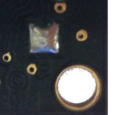
For volume orders, the TTL option
is available as no-cost factory installed jumper. The serial output is the most
accurate of the range outputs. Serial data sent is 9600 baud, with 8 data bits,
no parity, and one stop bit. V+ Pin 6 - Positive Power, Vcc: The sensor
operates on voltages from 2.5V - 5.5V DC. For best operation, the sensor requires
that the DC power be free from electrical noise. (For installations with bad
electrical power, a 100uF capacitor placed at the sensor pins between V+ and
GND will typically correct the electrical noise.)
GND Pin 7: Sensor
ground pin: DC return, and circuit common ground.

Dead Zone
Ultrasonic sensors have a dead zone in which they cannot
accurately detect the target. This is the distance between the sensing face and
the minimum sensing range. If the target is too close, the tone bursts leading
edge can travel to the target and strike it before the trailing edge has left
the transducer. Echo information returning to the sensor is ignored, because
the transducer is still transmitting and not yet receiving. The echo generated
could also reflect off the face of the sensor and again travel out to the
target. These multiple echoes can cause errors when the target is in the dead
zone.

Beam Angle
The beam cone angle values are the 3 dB points (i.e., points
at which the sensor signal is attenuated by at least 3 dB). Outside this cone
angle, the ultrasonic signal exists, but is rather weak. Targets may still be
detected. This can be experimentally determined.

Beam Cone Diameter
The ultrasonic sensor emits ultrasound wave
in a beam angle cone that eliminates side lobes. Target size versus beam spot
size is important. Theoretically, the smallest detectable target is one half
the wavelength of the ultrasonic signal.
Ultrasonic transducer is embedded, watertight, into the sensor
housing, in polyurethane foam. The transducer transmits a packet of sonic
pulses and converts the echo pulse into voltage. The integrated controller
computes the distance from the echo time and the velocity of sound. The
transmitted pulse duration and the decay time of the sonic transducer result in
a blind zone in which the ultrasonic sensor cannot detect an object. Normally,
the ultrasonic frequencies are between 65 kHz and 400 kHz, depending on the
sensor type and the pulse repetition frequency is between 14 and 140 Hz.


0 comments:
Post a Comment